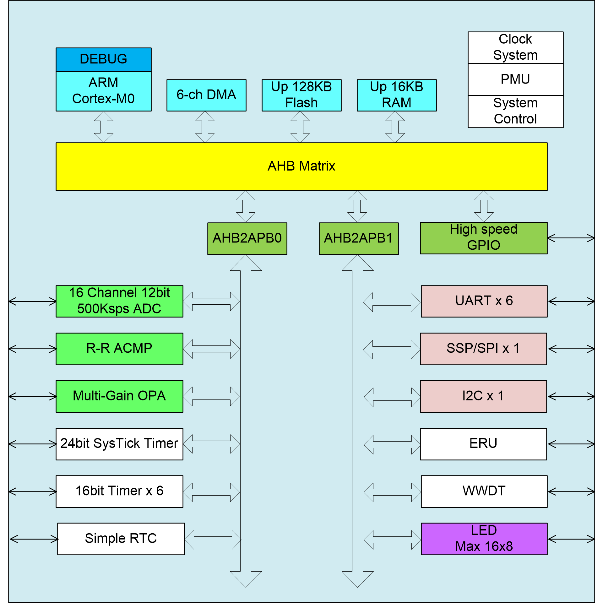
SC32F53128 is a series of 32bit MCU based on Cortex-M0 with maximum operating frequency 48MHz. It supports up to 128KB FLASH and 16KB SRAM, and integrates abundant timers, communication interfaces (6-ch UARTS, 1-ch SPI, 1-ch I2C) and high-performance analog front-end processing modules, such as 12bit 500ksps ADC, multistage gain adjustable OPA, etc. This IC is especially suitable for the new generation of white electricity products, office automation, IOT and other applications.
Features:
ARM 32bit Cortex-M0
Supports maximum operating frequency: 48MHz
Built-in Nested Vectored Interrupt Controller (NVIC)
Supports single cycle 32bit*32bit multiplication operations
Supports 6 channel DMA
Memory
Flash: up to 128KB (32Kx32)
Erase times: 20,000 cycles
data retention: 20 years
Up to 16KB RAM with parity check
Development support
Serial Wire Debug(SWD)
Supports memory and peripheral protection
Power supply and reset
Operating voltage: 2.0V~5.5V
Built-in LDO
Normal mode and low power mode optional
In normal mode, 1.5V and 1.7V optional
Built-in power on reset module(POR), typical reset release voltage: 1.8V
Built-in low voltage reset module(LVR), 4 level reset voltage optional: 2.3V, 2.7V, 3.7V, 4.1V
Built-in low voltage detect module(LVD), 8 level detect voltage optional: 2.4V, 2.7V, 3.0V, 3.3V, 3.6V, 3.9V, 4.2V, 4.5V
Clock system
External crystal oscillator: 1~20MHz(high frequency) or 32768Hz(low frequency)
Built-in low frequency 32KHz RCL, used as WDT independent clock source
Built-in high precision 16MHz RCH: ±1% @4.5~5.5V, -10~50C
Built-in phase-locked loop(PLL) with maximum output frequency 96MHz, which is provided to CPU and other high-speed peripheral modules after frequency 2 division
Supports external oscillation clock stop detection
Input/Output
Maximum 55 I/O ports
Configurable pull-up/pull-down and open-drain mode
PA ports support digital input filtering and input inverting
Configurable slew rate and 2-level drive strength(except for the I/O shared with SEG)
Configurable external interrupt input on all I/O ports, with edge and level triggering optional
Support LED drive with maximum 8*16 spot display
Timer
6 16-bit timers: TIM1/3/14/15/16/17
TIM1/TIM3 support 4-channel input capture/output comparison/PWM function, and TIM1's PWM output can further expand to support complementary deadtime insertion
WT can be realized by IWDT with maximum 30 second interrupt and 1second interrupt
2 Watchdog Timers: independent watchdog(IWDT) and window watchdog(WWDT)
SysTick timer: 24-bit decrement counter
Communication interface
6-channel UART: UART(1~6) with maximum baud rate 3Mbps
UART1/3 support flow control and UART2/4/5/6 only support two-wire communication
1-channel SPI: master mode 24 Mbit/s; slave mode 8Mbit/s
SPI interface can be remapped to three sides of the IC
1-channel I2C
Supports master-slave mode with maximum data rate 400ksps
Compatible with PMBUS and SMBUS specifications
I2C interface can be remapped to four sides of the IC.
Analog modules
1 high-performance 12-bit ADC with 16-channel input and maximum sampling rate 500ksps
Built-in two digital comparators
1 rail-to-rail analog comparator(ACMP)
1 operational amplifier(OPA) with configurable gain and 16-level of adjustable magnification from 1~10/12/14/16/24/32
Operating mode and current
Normal operating mode: 6.5mA @VDD=5V, MCLK=48MHz, analog modules and peripheral off
IDLE mode: 1.5mA @VDD=5V, MCLK=16MHz
STOP mode: 10uA @VDD=5V, analog modules and peripheral off, register and RAM data remain unchanged
Operating temperature
-40~85℃
Package
LQFP-64-10x10-0.5; LQFP-48-7x7-0.5;LQFP-44-10x10-0.8
Product Name | Package | Marking | Hazardous Substance Control | Packing Type |
---|---|---|---|---|
SC32F53128LB1G | LQFP-64-10×10-0.5 | 53128LB1 | Halogen free | Tray |
SC32F53128LL1G | LQFP-48-7×7-0.5 | 53128LL1 | Halogen free | Tray |
SC32F53128LB2G | LQFP-64-10×10-0.5 | 53128LB2 | Halogen free | Tray |